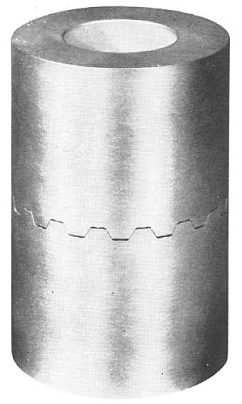
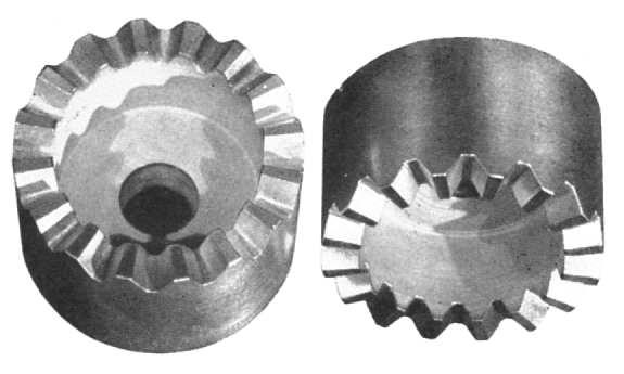
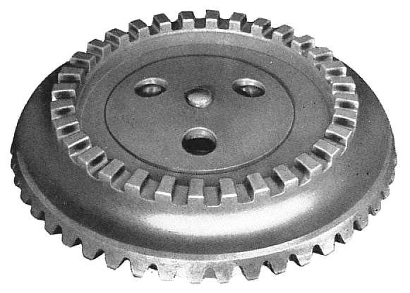
COUPLINGSCURVIC clutches and couplings have recently been developed to meet the need for extreme accuracy and maximum load capacity required in many applications where a fast rate of production is also demanded. The teeth of these clutches and couplings are cut and ground, or ground from the solid, on hypoid gear cutting and grinding machines. As a consequence, they possess the same high degree of accuracy of tooth spacing and the fine surface finish obtained in bevel gears. At the same time, the high-speed production machinery employed will turn out clutches and couplings at quantity rates comparable to those of automotive rear axle gears. The curvic design provides an accurate, light, compact, and self-contained connection in which the teeth both center and drive, as compared to other designs where the teeth drive only and other means of centering are necessary. The accuracy and uniformity are such that complete interchangeability is possible, affording the maximum ease of manufacture and assembly. Accordingly, in view of these advantages, the Curvic design opens up an entirely new field for coupling and clutch applications. Curvic couplings have teeth of radial direction and generally of parallel (constant) depth, which are cut or ground into the face of the part. These teeth can be produced with a wide range of pressure angles and usually with chamfered engaging surfaces. Generally, both sides of the teeth are produced in one chucking of the work by face-mill type cutters or cup-type grinding wheels on the Gleason Hypoid Gear Generators and Grinders. The type of Curvic coupling shown in illustration No. 23 is used for a combination of driving and alignment, the parts being bolted together. Illustration No. 23
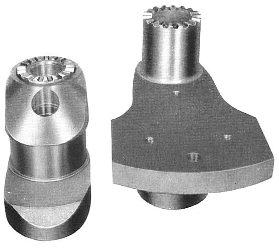
It is ideally suited for use in built-up crankshafts (Illustrations Nos. 24 and 25), and has proved very successful in many applications. Illustration No. 24
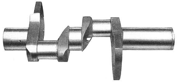
In the case of crankshafts, this type of coupling makes for easier design and manufacture and allows the use of solid connecting rod bearings in place of the split-type otherwise required, Also, the uniformity of the teeth obtained in grinding makes possible assembly of shaft from completely interchangeable parts. Illustration No. 25
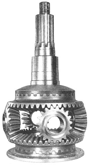
The teeth are made straight-sided -- that is, there is no profile curvature. A thirty degree pressure angle tooth has been found best for providing maximum surface contact, centering of the teeth, and alignment of parts in this application. The semi-universal type of coupling (Illustration No. 26) allows of a slight angular misalignment of shafts to a maximum of two degrees, as well as giving axial freedom. Illustration No. 26
It provides an ideal connection between engine and transmission. An outstanding marine application of this type of coupling is to be found at both ends of the Zerol bevel gear reversing unit, as shown in this illustration. In this application, a zero degree pressure angle is used in order to maintain constant backlash. Another type of coupling (Illustration No. 27) is used with an electric interlock as a safety unit to limit the torque in power drives. An example of its successful use is in power-operated control drives in aircraft. In this design, the two members of the clutch are held in engagement by a spring. By adjusting the spring tension, the amount of torque which can be transmitted without disengagement of the clutch can be controlled. At a given amount of disengagement of the clutch, the load is released by an electric switch. A thirty degree pressure angle is generally employed to give the most efficient operation with the smallest spring load. Illustration No. 27
Curvic couplings are generally cut and ground by the Uni-Arc method indicated diagrammatically in illustration No. 28, in which both sides of the teeth are produced with the same arc of the cutter or grinding wheel. Thus, both sides of the teeth have the same curvature -- either convex or concave. Illustration No. 28
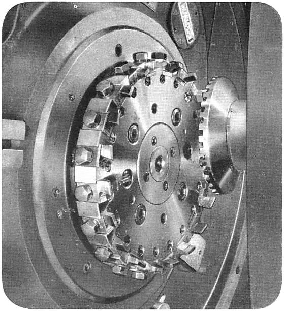
For the cutting operation, the blank is advanced into a rotating, circular face-mill type cutter, as shown by illustration No. 29, similar to that used for spiral bevel gears. The Gleason generator is set up so that the cutter sweeps across the face of the blank, cutting one side of one tooth at one point and the other side of another tooth in the same cutting arc at the second and absolutely separate point. Illustration No. 29
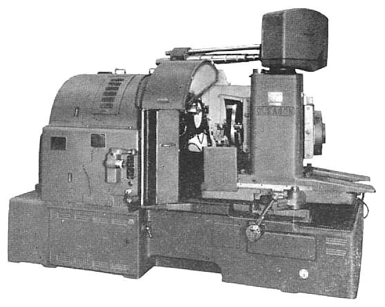
Each tooth is complete on both sides when the number of cuts equal to the number of teeth has been taken. Thus, the finished coupling teeth are produced at one chucking of the work, and the radial teeth produced dictate that the number of teeth and cutter diameter are interdependent. After the cutting operation, as seen in our next view (Illustration No. 30), the coupling teeth may be ground on the No. 17 Gleason Hypoid Gear Grinder, employing a cup wheel, comparable to the spiral cutter. Grinding produces the highest possible degree of accuracy and surface finish. The rate of production is extremely fast because of the continuous rotation of the spiral cutter or grinding wheel and the completely automatic cycle of the grinder, which has been previously referred to. Illustration No. 30
The same general rules applying to curved-tooth bevel gears must be followed in the design of Curvic couplings. The face width should not exceed three-tenths of the outside radius and preferably be limited to one-quarter, and the provision for cutter clearance means that there can be no projections above the root line on either sides of the teeth. The same advantageous localized tooth bearing produced in spiral bevel gears can be obtained in the cutting and grinding of Curvic couplings, as you will note in the detail view (Illustration No. 31). Illustration No. 31
In most cases, convex teeth are used on one member and concave teeth on the other. The concave teeth are produced by the outside surface of the cutter or grinding wheel, and convex teeth by the inside. The localized tooth bearing is secured by mismatching cutter or grinding wheel diameters. That is to say, the convex teeth of one member are produced with a cutter or grinding wheel of slightly smaller diameter than that used for the concave teeth of the other. The only exception is found in couplings having a very narrow face width, where sufficient tooth contact can be obtained with identical convex teeth on both members. |