CUTTING MACHINESComing now to the machines that are used for producing bevel and hypoid gears, we realize that we are on ground that is familiar to many of you, for you have here in the Naval Gun Factory quite a number of these machines, and men well skilled in using them to the best advantage. The basic problem of a bevel gear cutting machine is shown in illustration No. 4. Illustration No. 4
The two sides of a tooth (or tooth space as seen at A and A) show clearly that the profile shape is not the same for any two points along the tooth length, but constantly reduces in size, so that if carried far enough it becomes zero at the apex of the pitch cone, where all lengthwise elements of the tooth converge. Consequently, a formed tool or cutter cannot produce this tooth surface correctly. One method of overcoming this difficulty is shown in illustration No. 5. This shows a cutting tool carried by a slide reciprocating on an arm. The point of the tool always travels in its cutting stroke toward a point corresponding to the apex of the pitch cone of the gear being cut, while the arm on which the slide reciprocates is free to swing about two axes intersecting at this apex point. It is guided as it moves the tool in toward full depth of the tooth, by a former, which is an enlargement of the tooth profile shape, and is located at a greater cone distance from the apex than the tooth itself. This is the method used in the original machine by William Gleason in 1874. It is still used in a few machines whose size puts them out of the range of quantity manufacturing. Illustration No. 5
The generating method used in the two-tool machines of 1905 is illustrated in No. 6. It is seen that if a straight side cutting tool is rolled in proper kinematic relation to the gear blank, and successive cuts are taken in the various positions it assumes, it will envelop or generate a tooth profile. In this kinematic relationship the tool represents a tooth or a tooth space of a mating gear, which is straight sided for a rack or crown gear. The rolling motion is that of a crown gear meshing with its mating gear, and the profile shape produced with a straight sided tool is the well known involute form. Illustration No. 6
Illustration No. 7 shows the elements of the mechanism using this generating principle. When the crown gear and enlarged pinion roll together the two reciprocating tools for upper and lower sides of the tooth and the pinion being cut have the proper relative motion for producing the tooth shape. Illustration No. 7
This is seen again in illustration No.8. Illustration No. 8
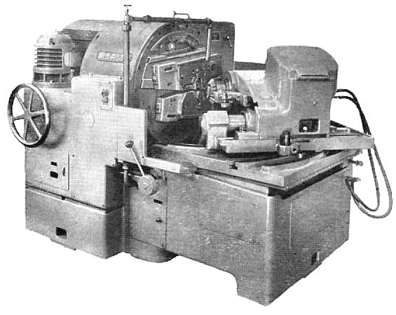
This generating motion is basic in the design of modern bevel gear cutting machines. Add to it a drive for the cutting tools, an indexing mechanism for bringing successive teeth into position for cutting, proper means for mounting the gear to be cut, controls for selecting the best feeds and speeds, arrangements for coolant, chip disposal, etc. and you are ready to cut bevel gears. In the tools all surfaces, including the sharpened face, are planes, making for simple manufacture and use. A typical machine of this type is the Number 14 Straight Bevel Generator shown in illustration No. 9. Illustration No. 9
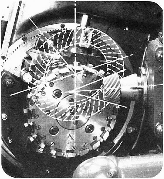
A recent most valuable improvement in this machine is the mechanism by which it produces Coniflex teeth having localized bearing as shown in illustration No. 10. This feature, long known and used to such advantage on spiral bevel gears, and now available on straight bevels, prevents concentration of tooth load at either end of the tooth even under slight misalignment, and increases tooth load capacity by avoiding possible breakage due to such concentration. Illustration No. 10
Machines of this two-tool type are available in sizes having capacity for cutting flat gears up to 35 1/2" diameter (this on No. 24 Straight Bevel Generator) and 1 1/2" D.P. While they can be used for rough cutting as well as finish cutting, special machines are available for the roughing operation in the most popular sizes of gears when the quantities warrant. |