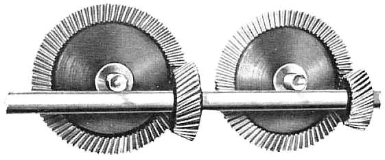
TYPESBevel and hypoid gears are suitable for transmitting power between shafts at practically any angle, speed and ratio of driver to driven gear. However, the particular type of gear best suited for a specific job is dependent upon the requirements of the operating conditions and on the mountings. STRAIGHT TOOTH BEVEL GEARSare, of course, the oldest form. (Illustration No. 1.) Illustration No. 1
But with improvement in speed and accuracy in production, and more particularly with the recent addition of the Coniflex feature (localized tooth bearing), they are still very much up to date and in many applications remain a first choice. They are recommended for peripheral speeds up to 1000 feet per minute where maximum smoothness and quietness are not of prime importance. In these applications, plain bearings may be used for radial and axial loads, (although anti-friction bearings are often preferred) and usually result in a more compact and less expensive design. Straight bevel gears being the simplest to calculate, set up, and develop, are ideal for small lots where fixed charges must be kept to a minimum. ZEROL BEVEL GEARShave curved teeth which are in the same general direction as straight teeth. (Illustration No. 2.) Illustration No. 2
They are spiral bevel gears with zero spiral angle and are manufactured on the same machines as spiral bevel. All Zerol gears have the advantage of localized tooth contact. They also have the advantage over straight bevels that they may have their tooth surfaces ground. Zerol bevels have the same thrust and tooth action as straight bevels and may be used interchangeably in the same mountings. They are recommended in place of straight bevel gears, (a) when a user has only spiral type equipment and wishes to cut gears without the added thrust of spiral bevels, which will be interchangeable with straight bevel gears so far as mountings are concerned; or (b) when he plans to change eventually to spiral bevel or hypoid gears. Also if the gears are to be hardened and distortion occurs during this process, Zerol gears may have their tooth surfaces ground, and thus restore the highest degree of accuracy. SPIRAL BEVEL GEARShave curved oblique teeth on which contact begins gradually and continues smoothly from end to end because of the overlapping feature. They have no more endwise sliding action than straight bevels.They have localized tooth bearing, easily controlled by slight changes in radii of curvature of mating tooth surfaces. They also can have their tooth surfaces ground. HYPOID GEARSare in many respects similar to spiral bevel gears except that the pinion axis is offset above or below the gear axis. With sufficient offset the shafts may pass each other, and a compact straddle mounting can be used on the gear and pinion. Hypoid gears are usually arranged so that the pinion has a larger spiral angle than the gear, with the result that the hypoid pinion is larger in diameter and stronger than the corresponding spiral bevel pinion. Hypoids have a sliding action along the lengthwise direction of their teeth, the amount being a function of the difference in the spiral angles on the gear and pinion. The tooth surfaces can be ground, as in the case of Zerol and spiral bevel gears. Spiral bevel and hypoid gears are especially recommended where the peripheral speeds are in excess of 1000 feet per minute or 1000 rpm, whichever occurs first. In many instances they may be used to advantage at lower speeds, especially in applications where extreme smoothness and quietness are desired. When peripheral speeds in excess of 8000 feet per minute are encountered, ground gears should be used. Both spiral bevels and hypoids have added thrust components due to the obliquity of the teeth, and this thrust must be provided for in the bearings. This calls for the use of anti-friction bearings. Spiral bevel and hypoid gears are also recommended for large reduction ratios to reduce the overall size of the installation. The continuous pitch line contact of spiral bevel and hypoid gears makes it practical to obtain smooth performance with a smaller number of teeth in the pinion than is possible with straight or Zerol bevel gears. For industrial applications, hypoids (Illustration No. 3) are recommended Illustration No. 3
Hypoids are almost universally used in passenger automobiles because of their smoother operation. The increase in strength of the pinion over that for the corresponding spiral bevel, together with the shaft offset, which assists in lowering the car body, are additional advantages. In the truck field, hypoids are being rapidly adopted because of the greater size and consequent strength of the hypoid pinion, which allows higher reduction ratios while still maintaining the required pinion shank size. There are numerous features in connection with the design and use of bevel and hypoid gears which require careful attention in order to obtain best results, such as selection of type of gear, gear size, choice of tooth numbers and pitch, tooth design, material and hear treatment, calculations for durability and strength, etc. These are amply covered in printed literature which is readily available, and aids are given for the proper solution of the problems involved. I shall not attempt to go into detail in these matters, but the Gleason Works invites inquiry on all problems where power is made to turn a corner, and will gladly furnish complete information to secure the best results. There is one matter, however, often not found in textbooks, which is of extreme importance. That is the question of accuracy in all the other operations in making a gear, as well as in the cutting of the teeth, and the proper mounting of the gear in final assembly, both as to position and as to rigidity of the supporting parts. The cutting of the teeth may be nearly perfect, as is possible in modern bevel gear cutting machinery. If, however, the bore of the blanks is large, or the locating surface for mounting is out of true, or the arbors for chucking are improperly designed or made, or the pair is not mounted and held in correct relative position in final assembly, the whole value of accuracy in cutting may be lost. These errors, though frequently not recognized, can be just as harmful as errors of the same amount in the cutting operation. Not many years ago unsatisfactory operation of a pair of gears was nearly always blamed on the cutting of the teeth. The makers of bevel gear cutting machinery gladly accept their responsibility for equipment that will produce accuracy in the product. On the other hand, years of experience and of investigation have demonstrated that accuracy in other operations and in mounting, and freedom from large deflections under load are quite as important. Unfortunately this has frequently been overlooked, and both the machine manufacturers and the users have suffered as a consequence. |